
These are the installation instructions for the RTM Fuel Tank Stud Repair Kit (1K-FuelTankStudRepairKit-1gAWD). This install kit is used on a 1g (1990-94) DSM AWD. The repair kit's function is to replace any damaged or missing studs with new bolts supplied in the kit.
Components Included in Repair Kit
1) C-shaped repair plates x 2
2) O-rings for above repair plates x 4
3) Repair plate installation bolts (5mm button-head stainless bolts) x 4
4) Allen key for above bolts
5) Stud replacement bolts (5mm hex-head stainless bolts) x 6
6) Nuts for above bolts x 2
7) 7/32" drill bit
8) piece of 120 grit emery paper
9) drill guide fixture (optional)
Principals of Operation of Repair Kit
The stock attachment system for the fuel pump sending unit involves the use of six 5mm studs that are permanently affixed to the top of the fuel tank. They are not threaded into place, they are welded/braized to the top of the tank and thus can't be easily replaced if they're ever damaged. The basic premise behind our repair kit is to replace any damaged studs with bolts. Seems too simple, there must be a catch, right? Well there is. The stud area on top of the tank is a complicated mixture of sheet metal, and as it happens, there's not enough "meat" to simply drill and tap a hole. So the solution: provide a tapped (threaded) hole underneath the sheet metal of the top of the tank. In a nutshell, that's what our repair kit does. How this is achieved is a bit complicated, but the basic principal behind it is really that simple.
The principal components of our repair kit are two identical semi circular steel plates (which we refer to as C-shaped repair plates) that are shaped to fit inside the fuel tank, underneath the stud area. See Photo 1 below. Together they form a circular structure beneath the stud area of your tank. (The reason a single circular plate is not used is that it would be unable to fit into the fuel pump opening). The simplest way of thinking of these repair plates is as structures that provide the thick metal "meat" that will accept a bolt from above (something the sheet metal of the stud area is unable to do). Each repair plate contains three threaded holes at precise locations. When installed in the appropriate place in the stud area, these threaded holes lie precisely beneath each stud (or missing stud) above it and the two plates (each accounting for three studs) accounts for all six studs in the stud area. The precise positioning of the repair plates requires that a number of holes above them be drilled at precise locations. This is achieved with the use of a drill guide fixture. Without a guide of some kind, it would be virtually impossible to drill holes into the sheet metal with the degree of precision required. This fixture mounts to the stud area on top of the tank and allows the drilling of precise holes. Refer to Photo 5 below for a good view of the drill guide fixture on top of the tank.
In a nutshell, the core elements of our repair kit are the two C-shaped repair plates and the drill guide fixture that makes their use possible.
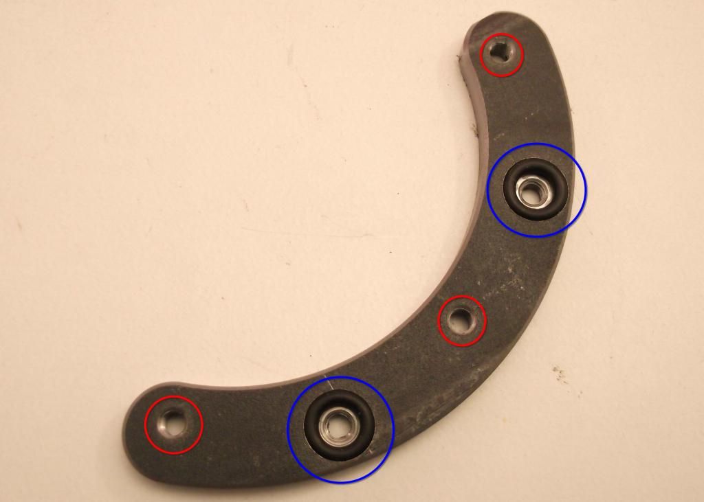
Photo 1. This is a closeup view of one of the C-shaped repair plates. Circled in red are the threaded holes designed to lie precisely below three studs (or missing studs). Circled in blue are the two threaded holes (surrounded by rubber o-rings) that allow the plate to be attached to the underside of the top of the tank. Two of these repair plates situated opposite each other account for all six studs (or missing studs) that attach the fuel pump sending unit (FPSU) to the tank.
Drain Fuel from Tank
Before you can do any work on the fuel pump sending unit area of your fuel tank, at the very least, you should drain any fuel from it. There are several methods of draining the tank but most involve removing the drain plug found at the bottom corner at some point in the procedure. Even preferable to merely draining your tank is to remove it entirely from your vehicle. This gives you a heck of a lot more room to work and just generally makes for an easier job. The reason for draining/removing your fuel tank is that the repair procedure involves several operations that can easily produce sparks and I think you can understand that sparks and fuel are a dangerous combination.
Notes on Debris Falling into Tank
Out of necessity, the installation of our repair kit is going to create a certain amount of debris all around the fuel pump opening. Bits of rusted metal, rust powder, metal debris from drilling operations, etc. are going to be created. You could attempt to prevent the debris from falling into the tank by covering the opening in some way, but since nearly all the repair operations involve work right in this area, it would make this cumbersome at best. It's almost certain that, inevitably, some debris will fall into the tank. This is not really cause for alarm. Afterall, with the FPSU removed from your tank, you've got a large-diameter opening that you could easily fit your hand in and pick up/wipe up any debris. You could use a magnet of some kind to pickup any ferrous debris and you could even use a shop vac (or any other vacuum cleaner that had a hose attachment) to vacuum up any debris. If your tank has been removed from the vehicle, you could even turn it upside down and shake out any debris. The point is, there are methods available to clean out your tank, so there's no need to unduly worry yourself over it. Also, any debris that escape your attempts to remove it is going to be caught by your pump filter or your main filter in the engine bay.
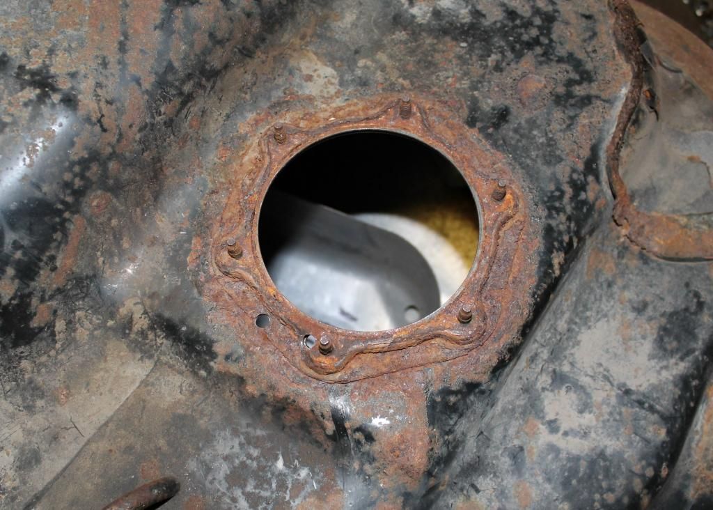
Photo 2. This is a photo of a typical sending unit area on the top of the tank with the sending unit removed. There are a couple of holes drilled in the stud area of this particular one, but just ignore those, they were part of a few R&D experiments we were trying.
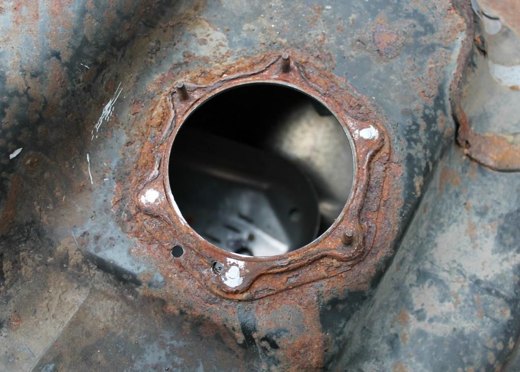
Photo 3. This is a photo of the stud area with three of the studs chopped off to simulate some broken/missing studs.
For the purposes of this installation procedure, we decided to simulate a typical fuel pump sending unit stud area by chopping off three of the original six studs. We feel this will allow us to give a good overall explanation of how our repair kit works.
Assess Condition of Stud Area on Tank
The first step in the installation procedure is to make an assessment of the condition of the stud area on top of the tank. You want to take a good look at each of your studs (assuming some remain) and decide if you want to keep them or not. If you feel any particular stud is too feeble to be able to be effectively used, you should probably consider removing it and replacing it with a new bolt from our kit.
Prepare/Cleanup Stud Area on Tank
Once you've decided on which studs you're going to retain (if any) the next step is to prepare/cleanup the stud area. You should remove as much corrosion as you can from this area. We recommend the use of a wire brush attachment and a drill to remove any loose rust and metal in this area. For any studs that are broken off/cut off, you'll want to file/grind down any protruding material flush with the rest of the surrounding metal. Photo 3 above shows the three studs we cut off filed down flush with the surrounding metal. In this photo, a wire brush has not yet been used. Removing any corrosion/loose metal is an important step so take your time and remove all you can.
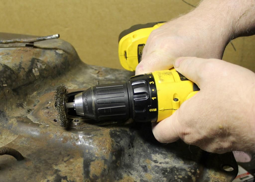
Photo 4. This photo shows a drill with wire brush attachment being used to clean up the stud area. (We actually did this step AFTER we drilled our holes using the drill fixture, but we recommend the cleanup be done earlier in the procedure--as discussed in the instructions).
Determine Orientation of Drill Guide Fixture
We've designed our repair kit to accomodate every scenario: from a single stud missing to all six. However, depending on how many studs are missing and where their positions are relative to each other, there can be a certain strategy to determining how your drill guide fixture is positioned to the top of your tank. Basically, you want to determine how many repair plates you'll need (either one or two) and what their positions should be. In order to make things a bit easier, we've engraved a few things into the top of the drill guide. The basic outline of the C-shaped plates are engraved into the guide so that you can easily visualize where they would end up going. Also, we've engraved small arrows that point to the four holes that are NOT associated with the six studs. Therefore, the six holes that do NOT have an engraved arrow pointing to them are the holes you will be lining up to your existing/missing studs.
The best way to visualize everything is by way of an example. Refer to Photo 5 below. In this photo, all the holes over existing/missing studs are coloured either pink or red. (The existing studs are circled in red, the missing studs circled in pink). They are also numbered in order 1, 2, 3 . . . 6. In this example, hole numbers 1, 3 and 6 are existing studs and hole numbers 2, 4 and 5 are missing studs. Note the engraved semi-circles (on the outside of holes 1 & 3 and holes 4 & 6) that indicate where the C-shaped pieces would be. In this example, the holes in the drill guide numbered 2, 4 and 5 (circled in pink) will be drilled. The two holes on the right, circled in blue, will also be drilled. These are the holes needed to attach a repair plate in position beneath stud positions 1, 2 and 3. Finally, the two holes on the left, circled in blue, will also be drilled. These are the holes needed to attach a repair plate in position beneath stud positions 4, 5 and 6. If, for example, all three studs at positions 4, 5 and 6 were present, there would be no need to use a repair plate on the left side since all the studs beneath it would be intact.
I suppose we could list every possible permutation of exisitng/missing studs and have a writeup for each one, but we feel that would unnecessarily complicate things. We think it's best if you use the engravings on the fixture, the example detailed here and the various photos in these instructions to give yourself a feel for how your particular repair should be handled. Of course, if you still feel uneasy about how to tackle your particular setup, you can contact us for assistance. All our contact info is available on our website.
Place Drill Guide Fixture on Stud Area
If you have one of our drill guide fixtures (either ordered with your kit or acquired previously) now is the time to position it on the stud area.
If you do NOT have a drill guide fixture we really cannot offer any suggestions in drilling your holes except to recommend that you build your own fixture. Theoretically, the positions could be calculated and measured, but it would involve some fairly precise measuring and some fairly precise drilling (and this would be very difficult to accomplish without the drill bit being "guided").
One side of the drill fixture has a large-diameter raised ring designed to snugly fit into the fuel pump opening in the centre of the stud area. Refer to Photo 6 below. It also has a series of holes drilled around the circumference, six of which exactly match the locations of the original studs and four of which are used to drill additional holes in the tank to fasten the C-shaped repair plates to the tank. Refer to Photo 5 below.
1) Using the strategy/decisions you made in the previous step on the orientation of the drill guide, place the guide over the stud area making sure to line up any existing studs with the corresponding holes in the fixture. (The six holes that do NOT have an engraved arrow pointing to them on the fixture correspond to the six stud positions on the top of the tank. They're circled in red and pink in Photo 5 below).
2) While sliding the fixture over any studs (as detailed in step 1 above) make sure to locate the raised ring in the centre of the fixture into the fuel pump opening in the centre of the stud area. Refer to Photos 5 & 6 below.
3) The raised ring of the fixture may be a bit snug pushing through the large fuel pump opening, but it should push down flat and true. If the resistance seems too great, make sure there aren't any burrs or other obstructions in the way.
The holes in the fixture are sized to fairly closely match the diameter of any remaining studs and the raised ring is sized to be a snug fit as well. The result is that once the fixture is fully pushed down flat against the top of the tank, it should sit in place fairly firmly (even if none of the original six studs are present).
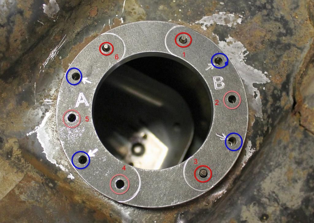
Photo 5. This photo shows the so-called "up side" of the drill guide fixture. It's the side of the fixture that faces up when placed on the stud area on top of the tank. The existing studs are circled in red and the "missing" studs are circled in pink. The holes used to fasten the C-shaped repair plates to the tank are circled in blue. Note the various things engraved into the fixture: the little arrows that point to the four holes that are NOT placed over any existing studs and the curved lines that mark the outlines of the C-shaped repair plates (that will end up being located on the underside surface).
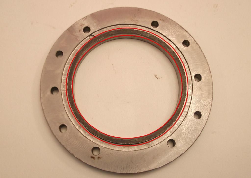
Photo 6. This photo shows the so-called "down side" of the drill guide fixture. It's the side of the fixture that's placed down against the top of the tank. The raised ring around the large hole in the centre (highlighted within the red circles) fits inside the fuel pump opening on the top of the tank.
Drilling Holes into Top of Tank
Finally, most of the hard parts are done. At this point, you should have assessed all your studs and decided which ones stay and which ones go. The entire stud area around the fuel pump opening should be fairly clean and free of loose and corroded metal and you should have positioned your drill guide fixture in place over the stud area on top of the tank. It might be best to take a few moments now and double check your setup and make sure everything appears the way you want it. While it isn't a fatal error to drill holes in the incorrect spot, it would certainly make life much easier if you didn't.
Once you're satisfied that your setup is ready to actually start drilling holes, you can begin.
First off, if NONE OF YOUR STUDS REMAIN IN PLACE, that is, if ALL SIX STUDS ARE MISSING, there is a slightly different procedure required which is detailed under the heading "Drilling Holes into Top of Tank: All Studs Missing". If this is the case with you, skip down to that heading.
Drilling Holes into Top of Tank: at Least 1 Stud Remaining
If you have at least one stud remaining, you can use the following procedure:
1) Take 7/32" drill bit supplied with your kit and insert into drill of your choice. In this case, a cordless hand drill should easily suffice.
2) If you have very few studs present, you may find the fixture has a tendency to vibrate and attempt to move about. If this is the case, we suggest steadying with one hand.
3) You will be drilling into multiple layers of thin sheet metal so the drill bit will have a tendency to get caught up. Best to take your time and, if necessary, reverse the drill out of the hole and re-start again. You may have to do this multiple times for stubborn holes. Take your time with each hole.
4) Drill out all the necessary holes. It should be noted that all the holes drilled (whether for a stud replacement or to bolt down a C-shaped plate) will be done with the same 7/32" bit.
5) Once all holes are drilled, remove fixture.
Drilling Holes into Top of Tank: All Studs Missing
If all six of your studs are missing it makes the placement of the drill guide a bit tougher. Because the drill guide has the raised ring that locates on the fuel pump opening, the guide will be centred over the stud area regardless of how many studs are in place. However, with no studs in place, the guide could be rotated around the centre in any orientation (whereas if even just one stud were present, the guide would be unable to rotate at all). So with no studs, the trick is to line up at least one of the six stud holes in the fixture directly over one of the original stud locations. There are probably several methods of accomplishing this, but here's our recommendation:
1) Before you place the fixture over the stud area, mark the centre of one of the original stud locations with marker or something similar.
2) Place the fixture over the stud area and, if necessary, rotate it until the mark lines up with one of the stud holes.
3) Take 7/32" drill bit supplied with your kit and insert into drill of your choice. In this case, a cordless hand drill should easily suffice.
4) Since there are no studs to prevent the fixture from rotating, you may find it has a tendency to vibrate and attempt to move about, therefore, we suggest steadying it with one hand.
5) You will be drilling into multiple layers of thin sheet metal so the drill bit will have a tendency to get caught up. Best to take your time and, if necessary, reverse the drill out of the hole and re-start again. You may have to do this a few times, so be patient and take your time.
6) Once you get this first hole drilled, thread one of the stud replacement bolts through the fixture and into the hole in the tank.
7) Thread one of the 5mm nuts onto the above bolt and snug it up. This should make the fixture much steadier for subsequent holes.
8) Carefully drill another stud replacement hole (preferably directly opposite the hole you just drilled) and similar to the first hole, use a bolt and nut in this hole to bolt the fixture to the top of the tank.
9) Once the fixture is bolted to the tank with the above two bolts and nuts, it should remain steady for all subsequent holes.
10) Drill out all the necessary holes. It should be noted that all the holes drilled (whether for a stud replacement or to bolt down a C-shaped plate) will be done with the same 7/32" bit.
11) Once all holes are drilled, remove bolts holding fixture down and remove fixture.
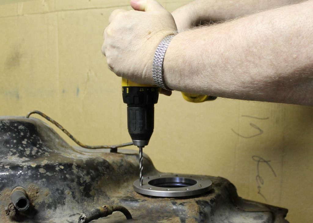
Photo 7. This photo shows the drill fixture in place on the stud area and a drill being used to drill the required holes into the top of the tank.
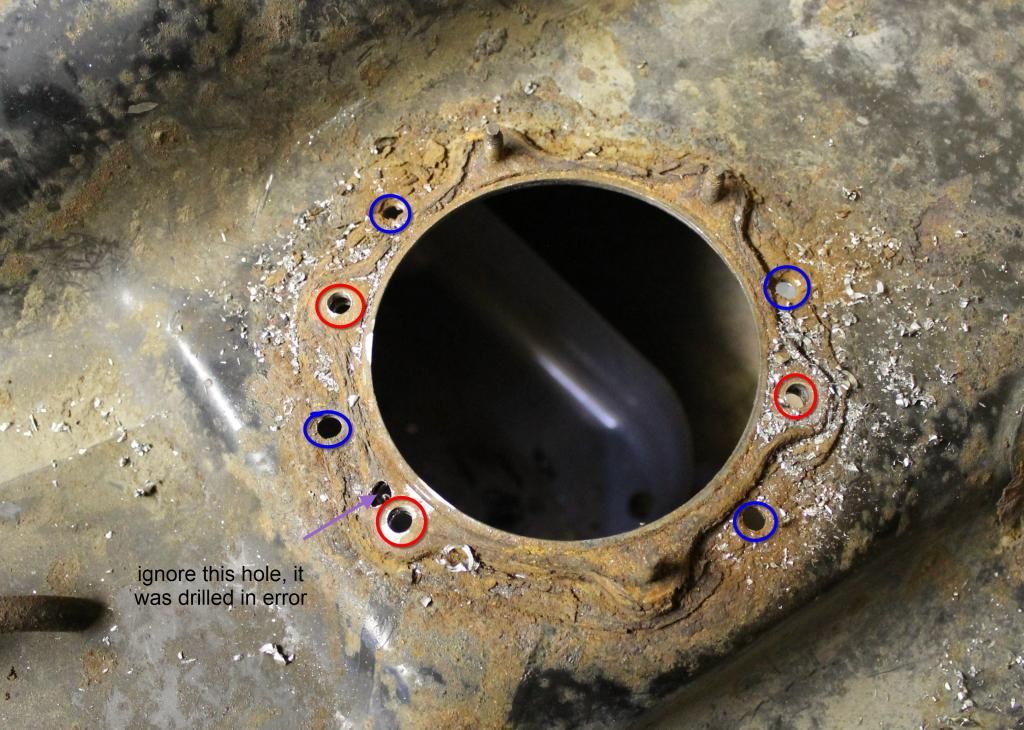
Photo 8. This photo shows the stud area after all the required holes have been drilled. We took the photo before removing any of the drill shavings to show that the drilling will produce quite a few metal shavings that will have to be dealt with. The holes circled in red are the places that used to be studs and the holes circled in blue are to be used to attach the C-shaped repair plates to the underside of the top surface, just beneath the stud area.
Remove All Burrs on All Holes Drilled
This step is a bit of a nuisance since access to the underside of the holes you just drilled is awkward at best. However, it is absolutely critical that this step is done, otherwise you may have fuel leaks where the C-shaped plates are bolted down. Photos 9 & 10 show some examples of how to remove the burrs.
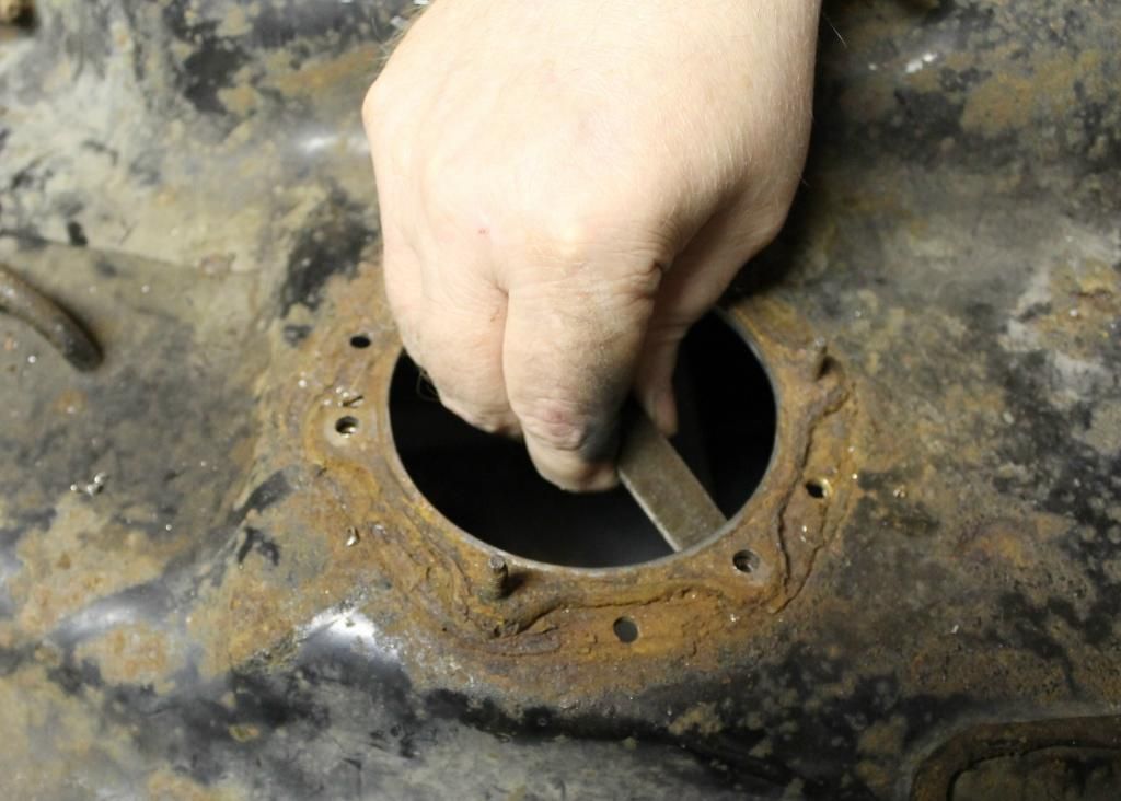
Photo 9. This photo shows us using a file to file down all the burrs on the holes we drilled. This is a bit of a nuisance, but it is a necessary step. In order for the O-rings on the C-shaped repair plates to seal properly, they require a nice flat surface, free of any protrusions.
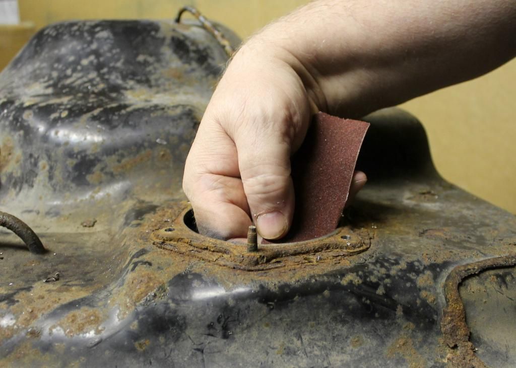
Photo 10. This is similar to the procedure in Photo 9 above, except that we're using a piece of emery cloth (sandpaper) to remove the burrs on the drilled holes. Anything you want to use is fair game, but it is important that all the burrs are removed.
Install C-Shaped Repair Plate(s)
Once all the holes have been drilled and the area inside the tank, on the underside of the stud area, has been cleared of any drill burrs and is determined to be flat and obstruction-free, the repair plates are ready to be installed. Refer to Photos 11 & 12 for details.
1) Install two O-rings into the two counter-sunk areas on one of the repair plates.
2) Get ready two 5mm button-head bolts.
3) Using one hand, slide the repair plate inside the tank, under the stud area. Remember, the side with the O-rings faces up.
4) Using your other hand, thread one of the 5mm button-head bolts into the appropriate threaded hole in the repair plate.
5) Thread the bolt in finger tight only.
6) Thread in the other 5mm button-head bolt into the appropriate threaded hole in the repair plate.
7) Thread in finger tight only.
8) Repeat steps 1-7 on the other repair plate if necessary.
It's important not to tighten the bolts holding the repair plate(s) at this point, they should be finger tight only. This is because it may become necessary to move the plate(s) around a bit when threading in some of the stud replacement bolts.
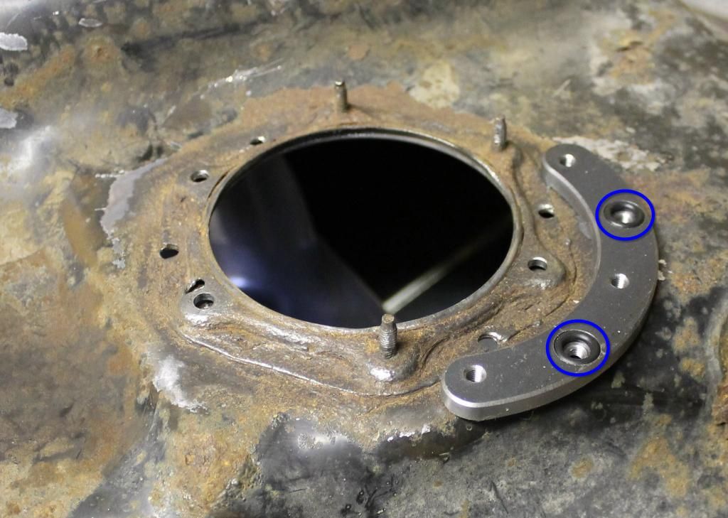
Photo 11. This is a photo showing one of the C-shaped repair plates (note the O-rings circled in blue which should face UP when installed in the tank). The orientation of this C-shaped plate is roughly in the orientation it will be in when it's inside the tank. Note that this plate contains threaded holes for up to three missing studs and also two threaded holes for the bolts used to attach the plate to the inside of the tank. This photo was taken after we gave the whole stud area a good going over with a wire brush attachment.
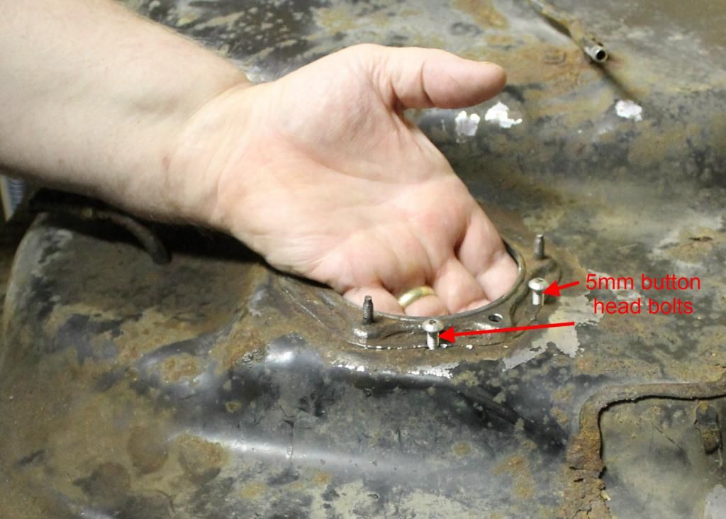
Photo 12. This photo shows us inserting one of the C-shaped repair plates into the tank and threading in two 5mm button-head screws in preparation to fastening it to the inside of the tank.
Test Insert All Stud Replacement Bolts
In order to ensure that the repair plate(s) are in the correct positions and that all the holes have been drilled correctly you should thread in the stud replacement bolts you intend to use. (The stud replacement bolts are hex-headed 5mm bolts). They should all thread in fairly easily without undue effort. If not, it could be that the repair plate is misaligned with the bolt. If this is the case, move the plate a bit to correct. Thread in all the stud replacement bolts you intend to use and tighten them finger tight. At this point, you should inspect the repair plates to ensure they haven't become misaligned with the fuel pump opening. That is, the inside edge of the plates are supposed to mirror the circular curve of the fuel pump opening without any part of the plates protruding into the opening. Refer to Photo 13 for details.
Tighten Down C-Shaped Repair Plate(s)
Once you're satisfied that the repair plate(s) are positioned properly and everything lines up correctly, you can now tighten down the two button-head bolts that fasten each repair plate to the tank. Torque to 10-15 ft/lbs. Refer to Photo 13 for details.
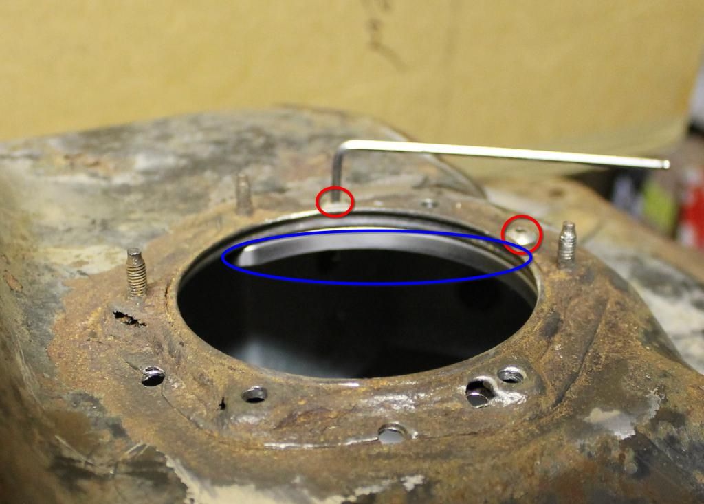
Photo 13. This photo shows us tightening down the two button-head screws (circled in red) that will fasten the C-shaped plate to the tank. The Allen key used for this is included with your repair kit. The C-shaped repair plate is circled in blue in the photo. Note its location inside the tank and how its curved shape exactly matches the fuel pump opening in the centre.
Install Fuel Pump Sending Unit
It should be noted that this repair kit will work with ANY fuel pump sending unit that attaches to the fuel tank using the stock studs. So, for example, it will work with one of our own sending units or with the stock sending unit. Of course the reason this is so is that the stud replacement bolts are in the exact same locations and of the exact same size as the original studs they're replacing. So anything that fit the stock setup will fit with this setup.
Detailing the installation of the sending unit is beyond the scope of these instructions. It can be a bit tricky, what with the fuel level float, pump pre-filter "tea bag" and various other attachments protruding in every direction. However, if you happen to have one of RTM's own FPSU's, we have a separate set of instructions in this same category in this Forum and, as it happens, installation of the stock FPSU is very similar.
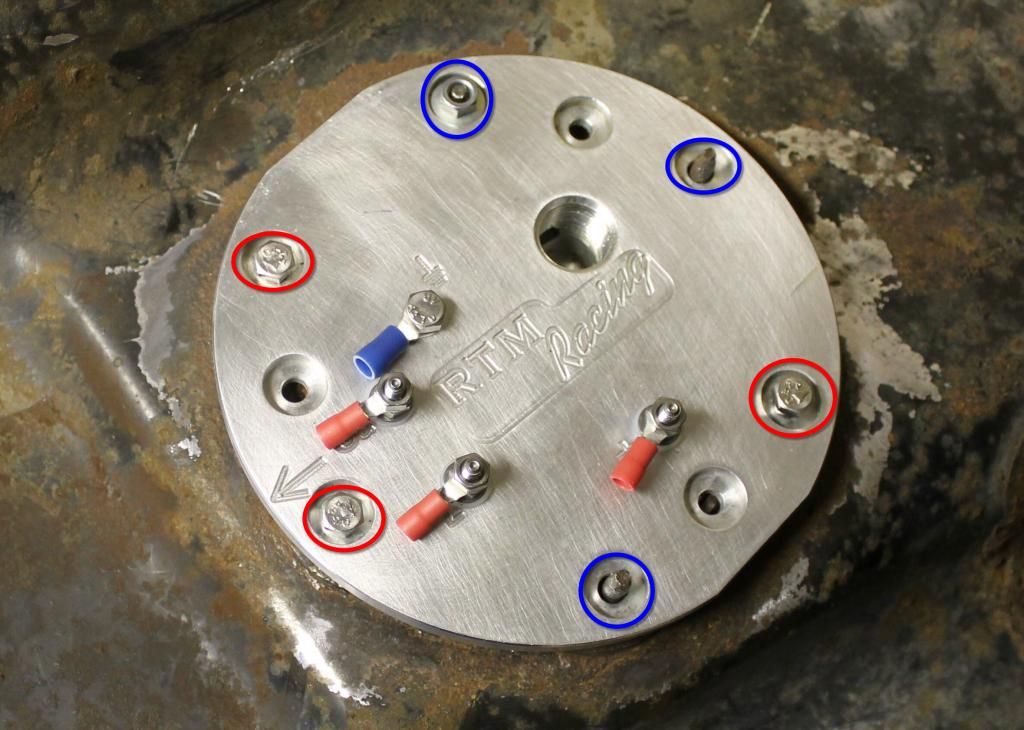
Photo 14. This photo shows one of our sending units in place in the tank. The bolts circled in red are new bolts supplied with the kit that replace the original studs that were missing/damaged. The studs circled in blue are original studs that are still in place. Note that one of the studs has a nut threaded onto it while the other two studs have no nut. This is simply to display what they look like. Eventually, you would want to add nuts to all remaining studs and tighten everything down in proper sequence. Note also that there are electric terminals attached to studs on top of the sending unit. This is simply how we ship our sending units to ensure the correct terminal goes on the correct stud. Note also that there are three "bare" countersunk holes with nothing attached to or protruding from them. These are the holes used to retain the sending unit gasket to the underside of the sending unit. For convenience, we took this photo without the gasket in place. Of course, this gasket should be in place on an actual installation.
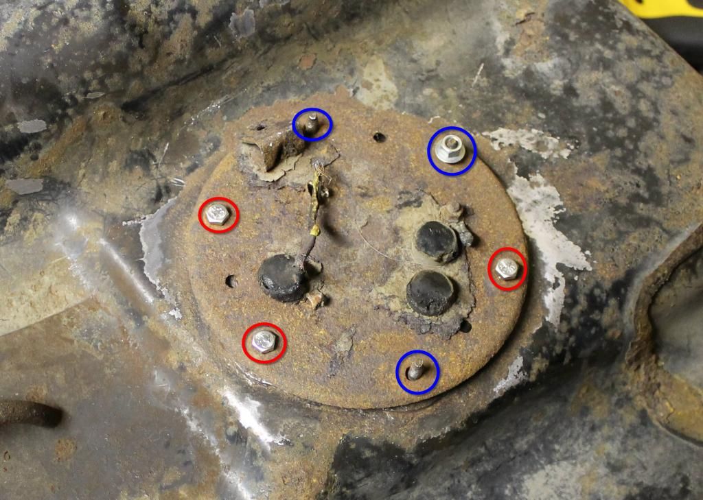
Photo 15. This photo shows a stock sending unit in place in the tank. The bolts circled in red are new bolts supplied with the kit that replace the original studs that were missing/damaged. The studs circled in blue are original studs that are still in place. Note that one of the studs has a nut threaded onto it while the other two studs have no nut. This is simply to display what they look like. Eventually, you would want to add nuts to all remaining studs and tighten everything down in proper sequence. Note also that there are three "bare" holes with nothing attached to or protruding from them. These are the holes used to retain the sending unit gasket to the underside of the sending unit. For convenience, we took this photo without the gasket in place. Of course, this gasket should be in place on an actual installation. You should also note that there's no fuel outlet (feed) line attached to the top of the sending unit. What a surprise, it snapped off when we were removing it from the tank! Certainly not unusual for one of these sending units.
Tighten Down All FPSU Bolts/Nuts
At this point, you're going to want to install nuts on any remaining studs and install replacement bolts in the other locations. Tighten down to about 2 ft/lbs. Yes, that's correct about 2 ft/lbs (which isn't a whole lot over finger tight).
|
Home
::
|