RTM Racing Fuel Pump Sending Unit (1K-RTM-FPSU-1gAWD)
INSTALLATION INSTRUCTIONS
NOTE: In the instructions below, we generally refer to the Fuel Pump Sending Unit simply by the abbreviation FPSU.
REMOVING OLD SENDING UNIT
We could give you the textbook version of fuel pump removal. Loosen this fitting, remove these six nuts, unplug this connector, etc. However, anyone that’s ever worked on a 15-20 year old car knows it’s never that easy. Parts tend to get rusted, seized, worn etc. making an apparently simple instruction like “loosen fitting” seem like a cruel joke. Since we at RTM Racing live in the real world just like everybody else, we’re going to offer some real world pointers.
NOTE: There are various guides and “how-to”s available online that give detailed instructions (some with photos) of the fuel pump removal procedure. We encourage you to refer to these as we feel the more info you have, the easier the job will be.
Removing Sending Unit Mounting Nuts
There are six small nuts that fasten your sending unit onto the top of the fuel tank. The studs they thread onto are of small diameter and quite fragile and if rust has had a chance to corrode them at all, they’ll be even more fragile. Therefore . . .
Before starting to turn any wrenches at all, WE STRONGLY RECOMMEND PRE-SOAKING THESE NUTS WITH PENETRATING OIL well in advance of attempting to crack them loose. In fact, the best procedure is to apply some once per day for several days. This is by far the single biggest aid to cracking them loose without snapping studs. We DO NOT recommend you skip this step. If you wish to retain your entire stock rubber hose, you should also pre-soak the connection between it and the flare nut on the hard metal feed line on the top of the sending unit.
NOTE: If you DO end up snapping off some or all of your studs, it’s not the end of the world. As it happens, RTM also makes a FPSU stud repair kit. Please refer to this Forum as well as our webstore for details.
Notes on Plumbing FPSU into Fuel Lines on Vehicle
The RTM FPSU comes with an -AN fitting (either -6 or -8) oriented either vertically up from the unit or horizontally forward from the unit. We chose an -AN fitting because we believe an -AN system makes for the cleanest, easiest fuel system plumbing. RTM happens to carry a number of fuel line upgrade kits that include -AN plumbing that are perfectly suited to plumbing in our sending unit. We believe it's best to use -AN plumbing from the sending unit to at least the fuel filter and preferably to at least the fuel rail inlet. The reasoning behind this is that if your stock sending unit has become corroded enough to warrant replacing it with a new unit, what shape would your hard metal fuel lines be in at the same stage? In any case, if you wish to retain some or all of your stock fuel line setup, our FPSU will accommodate it. It's a bit more complicated and time consuming, but it can be done. See details below, beginning at "Plumbing in RTM FPSU with Stock Fuel Lines".
Plumbing in RTM FPSU with -AN System
If you choose to plumb in our sending unit with -AN plumbing, congratulations, we feel you've made the best choice. If you've chosen to go with -AN plumbing to at least the fuel filter, your plumbing should be easy peasy because you need not concern yourself with any of the funky, corroded stock hard lines and hard line connections and are free to completely remove and discard the stock rubber hose and hard metal lines if you choose. Alternatively, you can keep the stock components in place and simply bypass them.
Removing the Stock FPSU Feed Line
The FPSU feed line is the approx 4" hard metal line at the top of the sending unit that begins with a 90-degree bend and terminates at a flare nut that threads into a fitting at the end of a long rubber hose. This line is notorious for rusting and then rupturing, splitting, cracking, etc when any pressure is put on it. If you're plumbing in your RTM FPSU with an -AN system, it's not necessary to retain any part of this hard metal feed line or the stock rubber hose it connects to and we recommend simply cutting the hard line somewhere near the top of the sending unit and cutting the stock rubber line somewhere along its length and discarding the resulting length of hard line/rubber hose.
Plumbing in RTM FPSU with Stock Fuel Lines
We don't really recommend trying to retain the complete stock rubber hose just downstream of the sending unit. It terminates at both ends with an M14x1.5 inverted flare female fitting. Our sending unit will come with an -AN fitting (either -6 or -8) and we know of no fitting that can convert -AN to M14x1.5 inverted flare female. There ARE ways to accommodate this situation if you really want to do it, but we feel it's more trouble than it's worth. We feel the best way of retaining the stock fuel lines is to remove the M14x1.5 metal fitting at the end of the stock hose and plumb into the bare end of the hose. For details on this method, please refer to "Splicing into Stock Rubber Hose". If you insist on retaining the entire length of the stock rubber hose (including the M14x1.5 inverted flare female fitting at the end), please refer to "Retaining Complete Stock Rubber Hose"
Splicing into Stock Rubber Hose
Simply cut the rubber line close to the end where it attaches to the old sending unit. Splicing into this hose end is a bit cumbersome since the distance between the outlet of our sending unit and the end of the stock rubber hose is about 4-5". In some cases, the hose may be able to be oriented in such a way as to reach the fitting at the outlet of the FPSU, but in most cases, you'd need to use a small length of additional rubber hose and a "hose mender” to attach the two rubber hose ends together. (A hose mender is a fitting with a hose barb and each end that attaches two lengths of rubber hose together and is said to "mend" two pieces of hose together). In any case, since the outlet of our sending unit will be an -AN fitting, you'll need a fitting (or combination of fittings) to convert -AN to 8mm hose barb. RTM carries a variety of such fittings to accomplish this.
Retaining Complete Stock Rubber Hose
In order to retain the complete stock rubber hose, you'll need to crack the flare nut to rubber hose end fitting connection loose. Hopefully, you'll have taken the earlier advice and soaked it well with penetrating oil. You will NOT need to re-use the stock hard metal line on the old sending unit, or flare nut at its end, so we recommend cutting this hard line right next to the flare nut at the end. This will allow you to have full access to the flare nut without any interference from the hard line. In this way you can use a 6-point socket to hold the flare nut, rather than an open end wrench. Once you've got the flare nut separated from its attachment point at the end of the stock rubber hose, you'll be left with an M14x1.5 inverted flare female fitting. The only style of fitting that mates with this is an M14x1.5 inverted flare male fitting. These are very rare in nature and generally occur only in the form of a flared metal tube and the matching M14x1.5 flare nut. The other consideration is that whatever fitting or combination of fittings you choose, must end up with an -AN female end to attach to the -AN male end of the fitting on our sending unit. As far as we know, your only options will be some kind of a custom fitting (or combination of fittings) to achieve the connection. As it happens, RTM carries a special M14x1.5 inverted flare female to -6AN male fitting. The use of this fitting would enable you to present two M14x1.5 inverted flare female connections adjacent to each other requiring only a double-ended M14x1.5 inverted flare male fitting to connect the two female ends together. Again, we know of no such fitting. However, it would be fairly easy to make a length of flared metal tubing with M14x1.5 flare nuts at each end that would connect the two female inverted flare ends together.
Disconnecting the Wiring Harness from Your Old Sending Unit
We probably don’t need to tell you this, but you should have your battery disconnected before working on this or pretty much any other electrical part of your car.
The RTM FPSU connects electrically to your vehicle's wiring via a series of terminals integrated into the top of the unit. There is no need to try to retain any of the stock terminals where they attach to top of the stock sending unit. You can simply cut each wire as close as possible to the terminal at the top of the sending unit. This will give you the longest length of wire with which to connect to your new sending unit.
For future reference, the colour key for each wire from your vehicle harness to your stock sending unit is as follows:
black with white stripe: power to the pump
black: ground to the pump
yellow: power to the fuel gauge
yellow with blue stripe: power to the low fuel light
Removing Old Sending Unit from Vehicle
At this point, everything that was attached to your old sending unit has been disconnected and you should now be able to remove it from the top of your tank. The rubber gasket between the top of the tank and the sending unit may cause some resistance, so it may require a little prompting, but it should come without too much effort. The sending unit cannot be pulled straight out completely because the float on the fuel gauge sending unit gets in the way. DON’T bend the wire the float is attached to, simply orient the assembly to enable the float to clear. At this point, do NOT discard the old sending unit since it's always useful to have a guide to work from and if you have not ordered a new fuel gauge sending unit with your RTM FPSU kit, you'll need to retain your current one and transfer it to your new unit.
PREPARING YOUR NEW SENDING UNIT
Installing Fuel Pump to FPSU
If you purchased your RTM FPSU kit with your choice of Walbro fuel pump(s), there’s no need to install your fuel pump(s) as your unit will come with them completely installed, ready to go. If you’ve purchased a Walbro pump(s) elsewhere or already own one, you’ll need to install the pump(s) to your new FPSU before installing the unit onto the top of your tank. The pump(s) installation will require the appropriate Walbro install kit(s). RTM carries the Walbro install kit(s). It will be the kit(s) specific to a 1g AWD application.
Procedure:
1) Remove the two small screws holding the plastic foot to the bottom of the aluminium upright, and remove the plastic foot. You'll need a 3mm allen key.
2) Remove any caps, o-rings, spacers or anything else from the top (outlet) port and bottom (inlet) ports on your pump(s).
3) Slide the sound insulating sock(s) supplied in the install kit over the pump(s).
3) Install the “tea bag” pre-filter(s) to the bottom of the pump(s), making sure to orient it such that the tab with the small hole engages with the small plastic protrusion at the centre of the pump(s).
4) Reinstall the plastic foot at the bottom of the pump(s), but don't screw it to the upright yet.
5) At this point, you'll want to determine the length of rubber hose required to connect to the hose barb ports above the pump area(s).
6) Cut the supplied rubber hose(s) to the appropriate length(s).
7) Remove the plastic foot again.
8) Install the rubber hose(s) you just cut onto the hose barb ports that protrude from the bottom of the main block of the sending unit.
9) Install one of the supplied small hose clamps over the hose(s) and just snug up the clamp. Do not yet fully tighten.
10) Slide one of the supplied small hose clamps over the bare end of the hose(s) and slide the outlet port of the pump(s) into the hose.
11) At this point, do not yet tighten the clamp(s).
12) Reinstall the plastic foot and screw it to the bottom of the aluminium upright making sure that the various protrusions on the bottom of the pump fit into the matching recesses in the plastic foot.
13) As you tighten down the foot, the pump(s) should push upward against the installed hose above them.
14) Once the foot is fully tightened to the upright, the hose should be in its "natural" position on the hose barbs.
15) At this point, you can tighten the hose clamps down.
16) Slide the supplied large hose clamp over the tea bag pre-filter(s) then over the pump(s) and aluminium upright to a point about halfway up the pump(s).
17) This will hold the pump(s) firmly in place against the upright.
18) Tighten clamp.
19) Install the electrical plug from the install kit onto the pump.
NOTES on RTM FPSU ELECTRICAL TERMINALS
Refer to photo 2 for details of the electrical terminals.
There are a total of five electrical terminals on each RTM FPSU. Two of them are ground terminals with one on the top surface of the unit and the other on the underside. In each case, these ground terminals are simply small hex-head bolts that thread into the aluminium structure of the FPSU. The other three terminals, however, are a bit more complicated. Each one passes completely through the top of the unit such that one end will be on the top surface (and thus on the exterior of the fuel tank) and the other end will be on the underside surface (and thus on the interior of the fuel tank). Each terminal is insulated from the aluminium of the sending unit by a special plastic bushing that shields the entire length of the terminal where it passes through the top structure. The whole assembly is held firmly together by a pair of nuts on either side of the aluminium top. It's critical that the two inboard nuts (labelled in the photo) are always firmly tightened against the plastic bushing against which they rest, otherwise the seal they provide may become compromised and fuel fumes may escape from the interior of the tank. Threaded on top of each of these nuts is another nut that is used to retain an electrical ring terminal. Thus, each terminal from bottom to top would contain (in this order): outboard nut, washer, electrical ring terminal, washer, inboard nut, washer, plastic bushing, washer, inboard nut, washer, electrical ring terminal, washer, outboard nut.
The RTM FPSU will come shipped with all the above components in place on each terminal. When you're ready to place a wire onto a particular terminal, you'll need to remove the outboard nut and washer, place the electrical ring terminal in place on the terminal stud and reinstall the washer and nut. When tightening the nut that retains the electrical ring connector (it will require a 7mm wrench by the way), the nut may resist tightening as the terminal stud may have a tendency to spin. As it happens, each terminal stud has an allen socket on the top end (which takes a 2mm allen key). Using an allen key on the stud, you can prevent it from turning as you tighten the nut. Also, for your convenience, we orient each stud to ensure that the allen socket faces the exterior of the unit which will enable you to remove and install wiring terminals on the exterior of the unit (once it's installed on your tank for example) without requiring access to the underside of the unit (or interior of your tank).
Wiring Fuel Pump to FPSU
Refer to photo 2 for details of the electrical terminals.
The connector included with your fuel pump install kit will have one black wire and one red wire. The red wire is power to the pump and the black wire is ground to the pump.
The RTM FPSU comes shipped with the nuts/bolts for all electrical terminals already loosely in place on the terminals. This is done for convenience so that you know where all the various nuts, bolts and washers go. In order to attach wiring connectors to the various terminals, you'll first need to remove the outboard nut and washer before attaching the wiring connector.
1) Using photo 1 below as a reference, install the ring terminal of the black wire to the bolt threaded into the underside of the top of the unit (circled in black in photo 1). There will be a small washer beneath the bolt head. This washer should go on top of the ring terminal and beneath the bolt head.
2) Remove the outboard nut and two washers from the stud circled in red in photo 1. This is the fuel pump power terminal.
3) Insert a 2mm allen key into the opposite end of the terminal stud to prevent the it from turning, and using a 7mm wrench, tighten the inboard nut firmly against the top of the unit. Refer to photo 2 for details.
4) Install a washer onto the stud, then the ring terminal of the red wire, then another washer, and finally the nut. (The final order of hardware on the stud should be: outboard nut, washer, ring terminal, washer, inboard nut, washer, plastic insulator, FPSU)
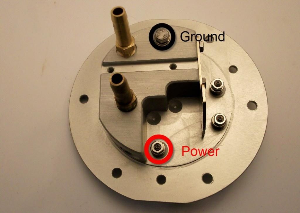
Photo 1. This photo shows where the fuel pump black ground wire (circled in black) and the fuel pump red power wire (circled in red) goes. In this photo, the aluminium upright has been removed to better show the terminals in question.
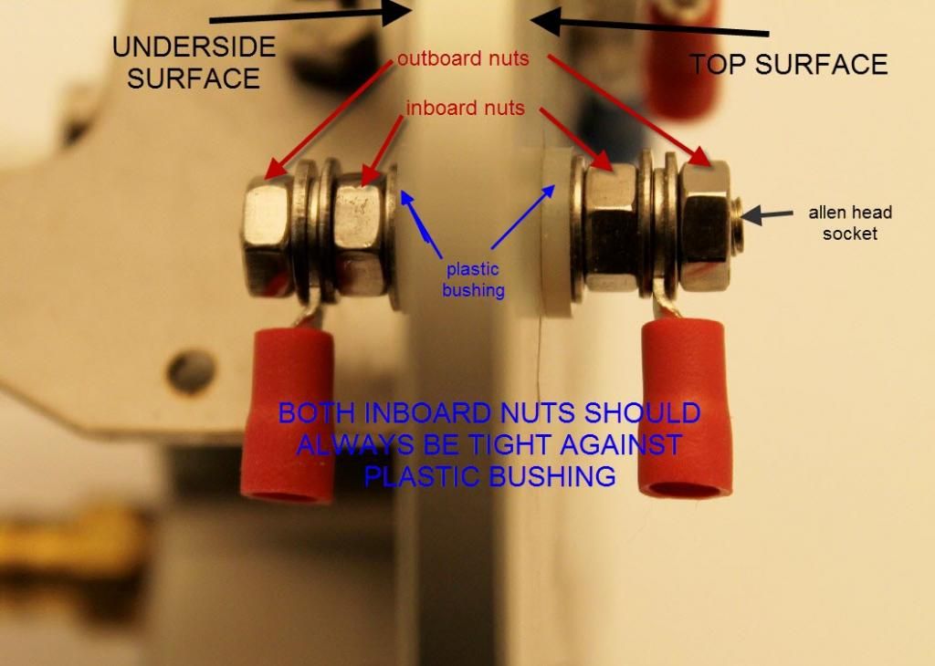
Photo 2. This photo shows the details of the electrical terminals on the RTM FPSU. It's critical that the two inboard nuts (labelled in the photo) are always firmly tightened against the plastic bushing against which they rest. This is due to the fact that the terminals pass completely through the sending unit and if the two inboard nuts are not sufficiently tight, the seal they provide may become compromised and fuel fumes may escape from the interior of the tank.
Installing Fuel Gauge Sending Unit into RTM FPSU
The fuel gauge sending unit is a device that sends a signal that operates your fuel gauge. Attached to it is a long wire-like projection with a plastic float on the end, and a sensor for the low fuel warning light. If you purchased a new fuel gauge sending unit along with your new RTM FPSU, we will have already installed it for you before shipping. If you purchased your new RTM FPSU without a fuel gauge sending unit, you’ll need to remove your old one from your old sending unit and install it on the RTM FPSU.
Removing Fuel Gauge Sending Unit from Old FPSU
The gauge sending unit is attached to the FPSU with two small M3 screws just underneath the top plate (see photo 3 below). It also has two wires which connect to terminals in the underside of the top plate.
1) Remove the two wires from their terminals.
2) Remove the two M3 screws (circled in blue in photo 2 below) that hold the gauge sending unit in place. These are often very tight and difficult to remove so take your time. Don't worry too much about stripping the heads because we include a new pair of allen-headed M3 bolts with your FPSU just in case your old ones are damaged.
3) Carefully remove the gauge sending unit, being careful not to bend or damage anything, as the unit is fairly fragile.
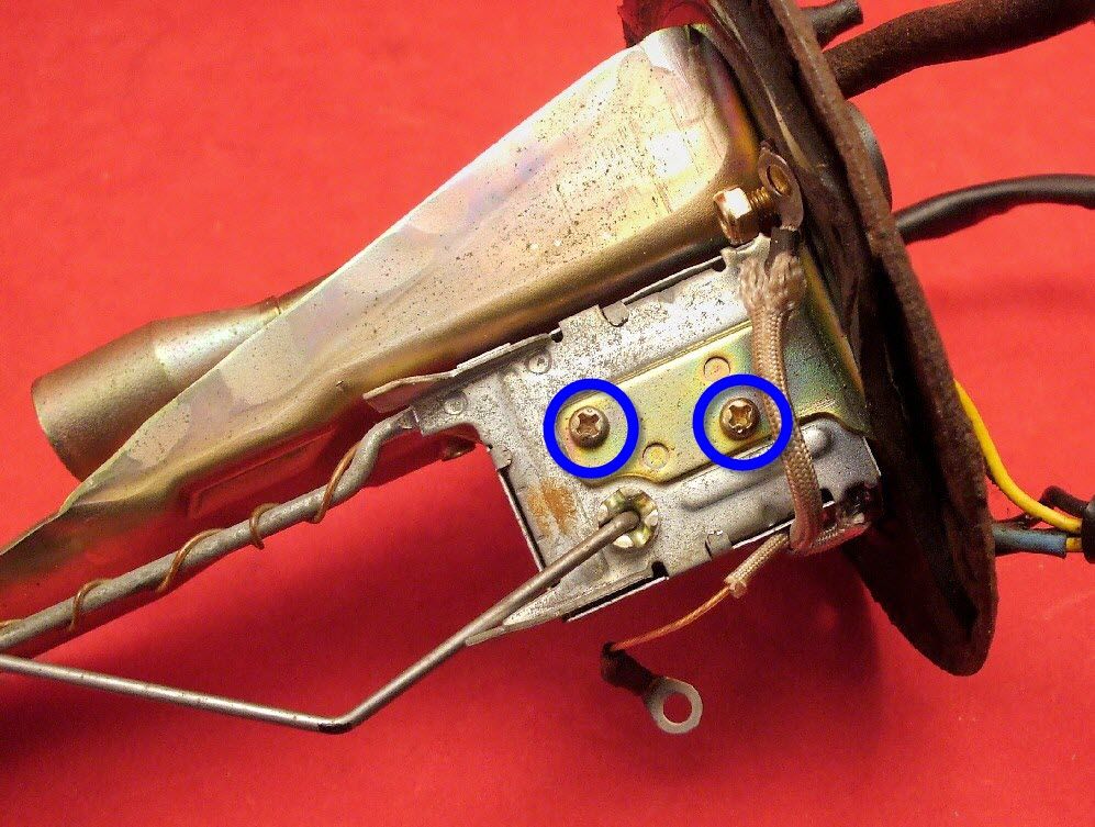
Photo 3. This photo shows the old fuel pump sending unit with the fuel gauge sending unit still in place. The bolt heads circled in blue are the ones that hold the gauge sending unit in place. They must be removed.
Installing Fuel Gauge Sending Unit into RTM FPSU
Using photo 4 below as a guide, carefully position the fuel gauge sending unit in place on the underside of the top of the RTM FPSU. It's generally easiest to install it with the FPSU unside down with the aluminium upright pointing upward. Use care when handling the gauge sending unit as it's fairly fragile.
1) Place the gauge sending unit in position behind the small sheet metal bracket and line up the mounting holes in the bracket with the threaded holes in the gauge sending unit. (At this point, it may be easier to lay the unit on its side to have better access to the bolt holes).
2) Using either the original M3 bolts from your old sending unit or else the new allen-headed bolts supplier with your kit, affix the gauge sending unit to the bracket. Tighten the bolts only finger tight. In fact, it's a good idea to keep all four bolts attached to the bracket only finger tight to help position gauge sending unit in place.
3) Once you're satisfied that it's in proper position, tighten all bolts down.
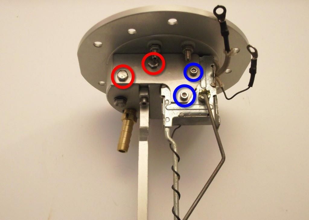
Photo 4. This photo depicts the fuel gauge sending unit as it looks installed in the RTM FPSU. This photo gives you an idea of the basic orientation of the gauge sending unit. Note the orientation of the float lever and other major structures and their relation to major structures on the RTM FPSU. The M3 allen-head bolts (circled in blue) are supplied with your kit and thread into threaded holes in your old gauge sending unit. The hex-head bolts (circled in red) affix the gauge sending unit bracket in place. When your RTM FPSU arrives, these hex-head bolts will be loose. This is to allow you to manipulate the gauge sending unit and bracket into position before tightening all four bolts down.
Wiring in Fuel Gauge Sending Unit into RTM FPSU
Use photo 5 below as a reference for the following procedure.
There are two wires, located on the fuel gauge sending unit, that need to be attached to electrical terminals on the underside of the RTM FPSU. One wire provides the signal to the fuel gauge unit on the instrument cluster and the other wire provides the signal to the "low fuel warning light" on the instrument cluster. It is important that each of these wires goes on the correct terminal. There are several ways of determining which wire is associated with each function, but we think the best method is to trace the wire from its end back to its source. One of the wires will trace back into the large metal box-like structure at the top of the gauge sending unit where it mounts to the underside of the FPSU. This wire is generally blue and is wrapped in a white sheath for some of its length. There is approximately 2.5" of this wire from where it exits the gauge sending unit box to the terminal connector at its end. This is the wire for the fuel gauge sending unit and goes on the "Ga" terminal (labelled as "Ga" and circled in blue in photo 4 below). The other wire is of considerably thinner gauge and is usually either white or black. It makes its way around the back of the gauge sending unit box and eventually twists its way down the length of a thin metal bar leading to a bulb-like sensor at the bottom. This is the wire for the "low fuel warning light" and goes on the "L" terminal (labelled as "L" and circled in white in photo 5 below).
The RTM FPSU comes shipped with the nuts/bolts for all electrical terminals already loosely in place on the terminals. This is done for convenience so that you know where all the various nuts, bolts and washers go. In order to attach wiring connectors to the various terminals, you'll first need to remove the lower nut and washer before attaching the wiring connector.
1) Remove the outboard nut and two washers from the terminal labelled as "Ga" and circled in blue in photo 4 below.
2) Insert a 2mm allen key into the opposite end of the terminal stud to prevent the it from turning, and using a 7mm wrench, tighten the inboard nut firmly against the top of the unit. Refer to photo 2 for details.
3) Install a washer onto the terminal.
4) Locate the wire you determined to be the "Ga" wire and install its wiring connector onto the terminal.
5) Install another washer onto the terminal and then the outboard nut and tighten finger tight. The final order of hardware on the stud should be: outboard nut, washer, ring terminal, washer, inboard nut, washer, plastic insulator, FPSU. Refer to photo 2 for details.
5) Remove the outboard nut and two washers from the terminal labelled as "L" and circled in white in photo 4 below.
6) Insert a 2mm allen key into the opposite end of the terminal stud to prevent the it from turning, and using a 7mm wrench, tighten the inboard nut firmly against the top of the unit. Refer to photo 2 for details.
7) Install one washer onto the terminal.
8) Locate the wire you determined to be the "L" wire and install its wiring connector onto the terminal.
9) Install another washer onto the terminal and then the outboard nut and tighten finger tight. The final order of hardware on the stud should be: outboard nut, washer, ring terminal, washer, inboard nut, washer, plastic insulator, FPSU. Refer to photo 2 for details.
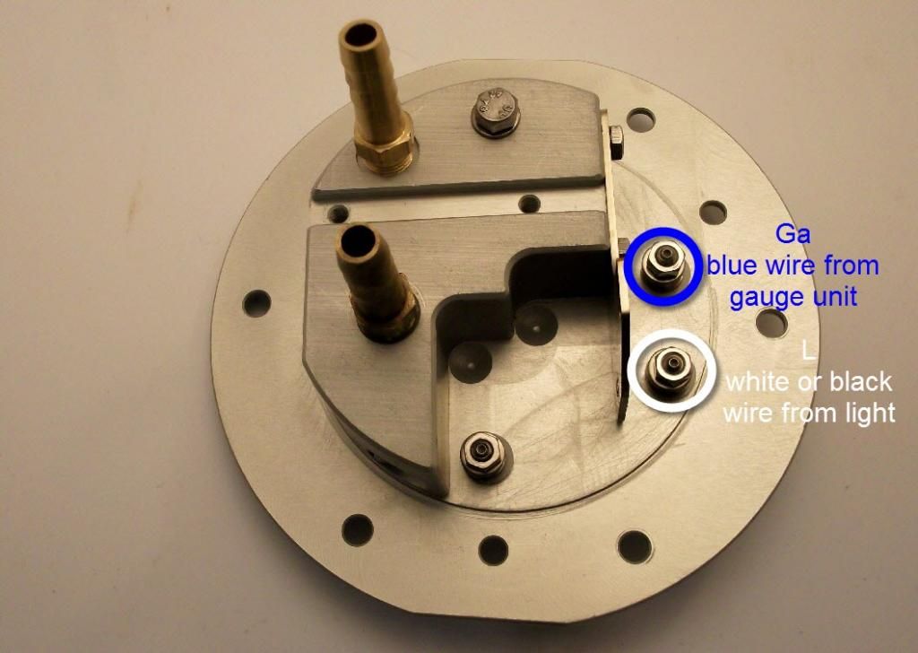
Photo 5. This photo depicts the location of the fuel gauge sending unit wiring terminals. The terminal labelled "Ga" (and circled in blue) is where the blue wire from the fuel gauge sending unit goes. The terminal labelled "L" (and circled in white) is where the very thin white or black wire from the low fuel warning light sender goes.
Installing Gasket to RTM FPSU
If you’ve ordered your RTM FPSU with a new gasket, the gasket will come already affixed to the unit. If you’ve decided to re-use your old gasket (which we strongly advise against) or if you’ve purchased a gasket elsewhere, you’ll need to install it to your FPSU. A proper OEM gasket comes with three rubber protruding “knobs” that fit into holes in the top plate of your new sending unit. These knobs ensure the gasket is located properly and remains in place while you install the complete assembly into your fuel tank.
1) With the FPSU upside down, place the gasket in position ensuring that the three protruding knobs are located in the appropriate holes (as shown in photo 6 below).
2) The knobs will be a fairly tight fit and will require considerable force to fully seat.
3) One method is to press the gasket from beneath the knobs firmly with your thumb. This method will probably not fully seat the knobs, but will seat them a good amount.
4) To seat the knobs further, turn the FPSU over and pull the knobs from above using a pair of pliers or a similar tool.
5) You'll know the knobs are fully seated when the gasket lays flush against the underside of the top around its entire circumference.
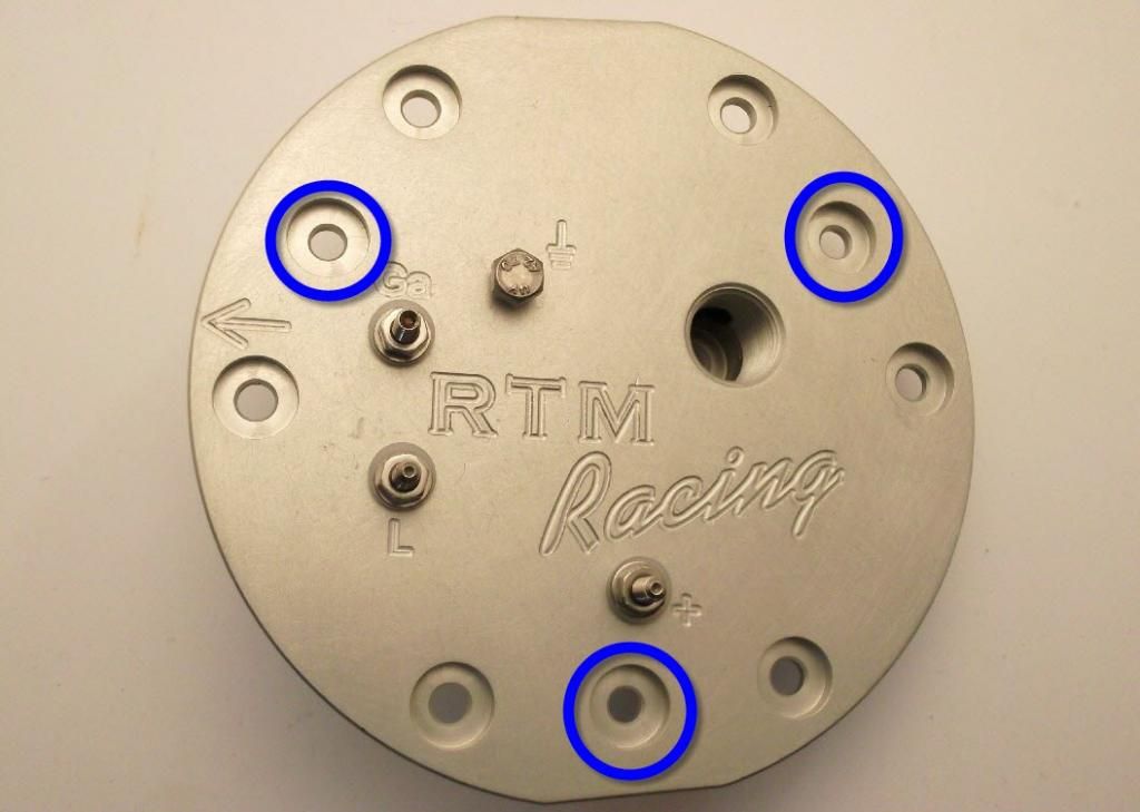
Photo 6. This photo shows the holes (circled in blue) where the three protrusions of the FPSU gasket are pushed through from below.
INSTALLING SENDING UNIT into VEHICLE
At this point, you've got everything installed onto your RTM FPSU: fuel pump(s), fuel gauge sending unit and FPSU gasket. Now it's time to install the whole assembly into your tank.
Procedure
1) The first thing you should do before beginning the actual install is to clean the area around the top of the tank where the FPSU will sit. You don't want any rust, debris, metal burrs, etc that may prevent the gasket from sealing properly.
2) Once you're satisfied that you've got a good clean area in which to mount your FPSU you're ready for the actual install.
3) Using photo 7 below as reference, make note of the arrow engraved in the top of your FPSU. This shows the general orientation of your unit in the tank.
4) The fuel level float and the metal arm which it's attached to present the biggest challenge to installing your unit because they protrude the furthest and in a very awkward orientation.
5) Therefore, start by inserting the float into the sending unit opening first. There are several structures inside the tank which will tend to interfere with the sending unit. The fuel return pipe, which enters just forward of the FPSU opening, continues downward into the tank near where the bottom of where the FPSU goes. The float, float arm, pump pre-filters, etc will all have a tendency to contact this pipe and prevent a smooth install. Therefore, you may need to manipulate the FPSU assembly in various orientations to clear this pipe. Be patient, it can be done.
6) Assuming you're able to manipulate the unit to avoid all the various internal structures, the sending unit should eventually drop fairly easily into place on the top of the tank. At this point you'll want to ensure the arrow engraved into the top of the FPSU is pointing towards the front of the vehicle (refer to photo 7 for details). If it isn't, you'll have to reposition the unit until it does. This may involve removing it from the tank completely and starting over, so be prepared for that.
7) Once the FPSU is in place and you're satisfied that it's sitting properly and the gasket is seated correctly and appears proper, begin tightening the six fasteners that hold the unit to the top of the tank. You should tighten them only finger tight initially to ensure the gasket is sealing correctly and there is no unusual resistance.
8) Once you're satisfied with everything, tighten all fasteners down.
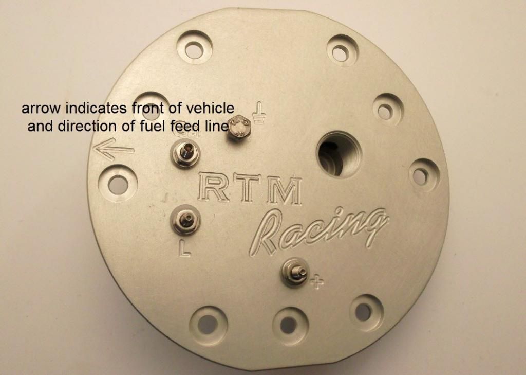
Photo 7. This photo shows the arrow that's engraved into the top surface of the RTM FPSU which indicates the basic orientation of the sending unit (front of vehicle in direction of arrow) and also the direction of the fuel feed line (whether stock or otherwise).
Wiring in RTM FPSU
Now that you've got your FPSU installed it's time to wire it up to your vehicles wiring.
Refer to photo 8 below for details.
Listed below are the four wires from your vehicle's wiring that are to be connected to the RTM FPSU. The list also includes each wire's function and eventual location on the RTM FPSU. However, at this point, there's no need to concern yourself with anything other than the wire colour. The RTM FPSU will have included ring terminals attached to terminals on top of the unit. Remove these ring terminals by removing the top nut on each stud. Place the nuts and washers aside (they will be used later). Two of the ring terminals will be for 14-16 gauge wire (with blue insulator) and two will be for 18-22 gauge wire (with red insulator).
black with white stripe = power to the pump = terminal with "+" symbol engraved next to it
black = ground for all power terminals = terminal with ground symbol engraved next to it
yellow = power to the fuel gauge = terminal with "Ga" engraved next to it
yellow with blue stripe = power to the low fuel light = terminal with "L" engraved next to it
1) Locate the black with white stripe wire (which is the wire for the power to the pump) and crimp on one of the blue ring terminals.
2) Locate the black wire (which is the wire for FPSU ground) and crimp on one of the blue ring terminals.
3) Locate the yellow wire (which is the wire for power to the fuel gauge) and crimp on one of the red ring terminals.
4) Locate the yellow with blue stripe wire (which is the wire for power to the low fuel light) and crimp on one of the red ring terminals.
Before attaching any wiring to the electrical terminals on the top of the sending unit, it's important that the terminals be checked to ensure they are firmly in place.
See "Notes on RTM FPSU Electrical Terminals" below for details.
NOTES on RTM FPSU ELECTRICAL TERMINALS
Refer to photo 2 for details of the electrical terminals.
There are a total of five electrical terminals on each RTM FPSU. Two of them are ground terminals with one on the top surface of the unit and the other on the underside. In each case, these ground terminals are simply small hex-head bolts that thread into the aluminium structure of the FPSU. The other three terminals, however, are a bit more complicated. Each one passes completely through the top of the unit such that one end will be on the top surface (and thus on the exterior of the fuel tank) and the other end will be on the underside surface (and thus on the interior of the fuel tank). Each terminal is insulated from the aluminium of the sending unit by a special plastic bushing that shields the entire length of the terminal where it passes through the top structure. The whole assembly is held firmly together by a pair of nuts on either side of the aluminium top. It's critical that the two inboard nuts (labelled in the photo) are always firmly tightened against the plastic bushing against which they rest, otherwise the seal they provide may become compromised and fuel fumes may escape from the interior of the tank. Threaded on top of each of these nuts is another nut that is used to retain an electrical ring terminal. Thus, each terminal from bottom to top would contain (in this order): outboard nut, washer, electrical ring terminal, washer, inboard nut, washer, plastic bushing, washer, inboard nut, washer, electrical ring terminal, washer, outboard nut.
The RTM FPSU will come shipped with all the above components in place on each terminal. When you're ready to place a wire onto a particular terminal, you'll need to remove the outboard nut and washer, place the electrical ring terminal in place on the terminal stud and reinstall the washer and nut. When tightening the nut that retains the electrical ring connector (it will require a 7mm wrench by the way), the nut may resist tightening as the terminal stud may have a tendency to spin. As it happens, each terminal stud has an allen socket on the top end (which takes a 2mm allen key). Using an allen key on the stud, you can prevent it from turning as you tighten the nut. Also, for your convenience, we orient each stud to ensure that the allen socket faces the exterior of the unit which will enable you to remove and install wiring terminals on the exterior of the unit (once it's installed on your tank for example) without requiring access to the underside of the unit (or interior of your tank).
Procedure
At this point, all the outboard nuts and washers on each electrical terminal should be removed and each remaining "bare" terminal should have been checked to ensure it is firmly in place (using method described in "Notes on RTM FPSU Electrical Terminals" above).
Use photo 8 below as a guide to the following procedure.
1) Install a small washer over each of the "bare" electrical terminals.
2) Place the ring terminal of the black with white stripe wire over the terminal engraved with the "+" symbol. This is fuel pump power.
3) Install another small washer.
4) Install a nut and tighten finger tight.
5) Place the ring terminal of the yellow wire over the terminal engraved with "Ga". This is the fuel gauge power.
6) Install another small washer.
7) Install a nut and tighten finger tight.
8) Place the ring terminal of the yellow with blue strip wire over the terminal engraved with "L". This is the low fuel light power.
9) Install another small washer.
10) Install a nut and tighten finger tight.
11) Remove the hex-head bolt from the location with the ground symbol engraved next to it. This is the ground terminal.
12) Install a small washer under the bolt head.
13) Place the ring terminal of the black wire over the bolt and reinstall bolt back into threaded hole and tighten finger tight.
At this point, confirm your wiring is correct using the following guide:
black with white stripe = power to the pump = terminal with "+" symbol engraved next to it
black = ground for all power terminals = terminal with ground symbol engraved next to it
yellow = power to the fuel gauge = terminal with "Ga" engraved next to it
yellow with blue stripe = power to the low fuel light = terminal with "L" engraved next to it
Once you're satisfied your wiring is correct, tighten all the terminals down. When tightening the three terminals that use studs, it's always best to prevent the stud from turning by inserting a 2mm allen key into the end of the stud while tightening the nut.
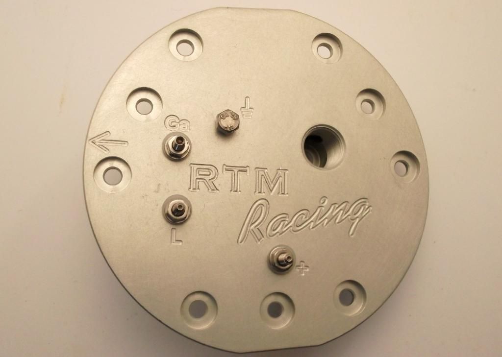
Photo 8. This photo shows the four terminals with their relevant labels engraved into the top surface to make identifying them easier. The universal symbol for ground indicates the ground terminal, the "+" symbol indicates the fuel pump power terminal, "Ga" indicates the gauge sending unit terminal, and "L" indicates the low fuel warning light terminal.
PLUMBING SENDING UNIT into FUEL SYSTEM
The RTM FPSU comes with your choice of a -6AN or -8AN outlet oriented either vertically up or horizontally forward.
It's really up to you how you wish to plumb in your fuel feed line from your sending unit but we can give you a couple of pointers.
In general, with the -AN vertical fitting, the feed line is most easily plumbed in with use of a 90-degree hose end.
In the case of the -AN horizontal fitting, in general, the feed line is most easily plumbed in with use of a straight hose end.
Also, we should point out, that in the case of the horizontal fitting, the -AN portion of the fitting can be swivelled 360-degrees to orient it in any direction you wish.
TESTING INSTALLATION
At this point, your sending unit has been installed and fastened to the top of the tank, all the necessary wiring has been completed and checked and your unit is plumbed into you vehicle's feed line. It's now time to test everything out.
The first thing you'll need to do is reconnect your battery (which should have been disconnected throughout the procedure).
Start your engine up and look for fuel leaks. Pay close attention to the gasket connection between FPSU and the top of the tank and your fuel feed connections.
WE HOPE YOU ENJOY YOUR BRAND NEW RTM RACING FUEL PUMP SENDING UNIT!!
|
Home
::
|