INSTALLING VR4 4-PISTON BRAKES ON A DSM/EVO1-3
NOTE: The following procedure is valid for a 1g DSM, 2g DSM or EVO I-III. The photos are of a 2g DSM, but the procedure is the same for all above vehicles.
Components Included in RTM VR4 Brake Upgrade Kit
1) RTM-made caliper mounting bracket x 2
2) knuckle-to-bracket mounting bolts (M12-1.75 x 30) x 4
3) caliper-to-bracket mounting bolts (M12-1.75 x 35) x 4
4) M12 lock washers x 8
5) M12 flat washers x 12
6) hubcentric rings x 4 (optional)
7) VR4 calipers x 2 (optional)
8) 13" Cobra rotors x 2 (optional)
9) brake lines (optional)
Removing Current Brakes
The installation of VR4 brakes requires that virtually every component of your brakes be replaced. That is, the rotors, calipers, pads and pad brackets all are replaced with different components than came stock on your car. The brake dust shield will also either have to be removed or modified to accommodate the larger rotor. The only component that MIGHT be retained is the brake lines. (This is only true in the case of a 1g DSM. 2g DSM or EVO1-3 must replace the brake lines as well).
We recommend working on one side of the car at a time, in case it becomes necessary to refer to your current brake setup.
The first order of business is to completely remove your entire caliper assembly (which includes your pads and pad bracket). We don't really recommend that you keep it attached to the brake line and tied off to a nearby suspension component since it will tend to get in your way. We recommend complete removal.
Then remove your rotor.
At this point, you should remove any rust or debris from your hub that would interfere with the mounting of your new rotor. You should especially focus on the hub protrusion which is where either your hubcentric ring or the centrebore of your rotor will mount.
Preparing Caliper Mounting Ears of Knuckle
In order to mount the RTM-made bracket to your steering knuckle, it's necessary that the caliper ears of your knuckle have a flat and true surface on both the front and back sides. Oftentimes there will be rough casting protrusions surrounding the bolt holes. These should be removed with a file or similar tool. It will be necessary to remove any protrusion that interferes with the bolt head on the back side of the mounting ears (see Photo 2) and any protrusion that interferes with the RTM-made bracket on the front side of the mounting ear (see Photo 1).
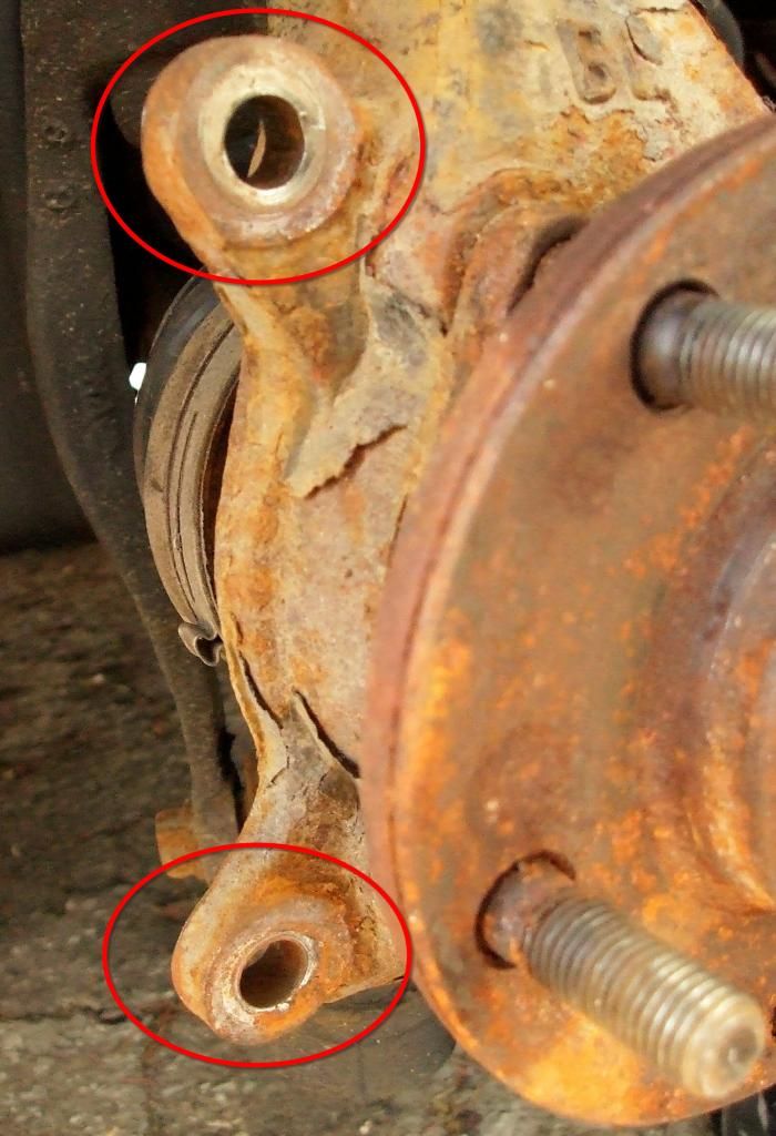
Photo 1. The areas circled in red indicate the frontside of the caliper mounting ears that should be free of any protrusions, allowing the RTM-made bracket to be bolted down flat and true.
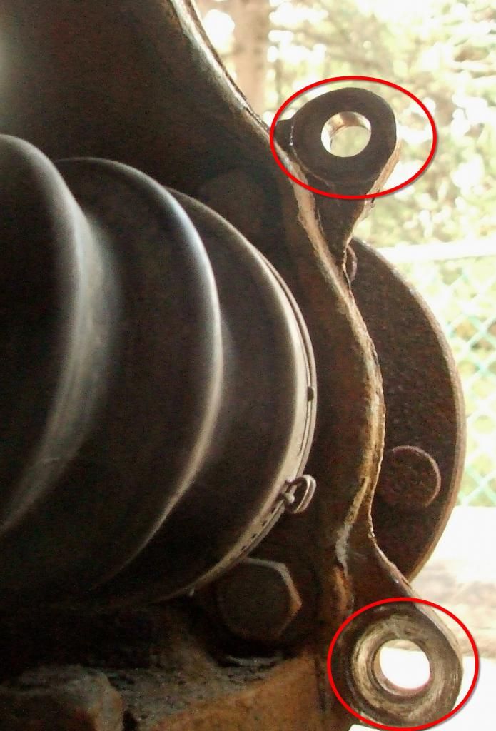
Photo 2. The areas circled in red indicate the backside of the caliper mounting ears that should be free of any protrusions, allowing the underside of the bolt heads of the knuckle-to-bracket mounting bolts to lay flat and true.
Mounting RTM-Made Brackets to Steering Knuckle
There are two RTM-made brackets included with your upgrade hardware kit that are used to mount VR4 calipers to your knuckle. One is used per each side of the vehicle.
1) Place one of the RTM-made brackets on the FRONT of the caliper mounting ears of one of your knuckles such that it's oriented as in Photo 3.
2) Install an M12 lock washer under the head each of two M12 x 30mm bolts.
3) Working from the back side of the knuckle mounting ears, pass the two above bolt/lock washer assemblies through the mounting ears and thread them into the appropriate threaded holes in the RTM-made bracket. (Refer to Photos 3 & 4 to determine which threaded holes on the bracket to use. You can also refer to Photos 1 & 2 for a view of what the front sides and back sides of the caliper mounting ears look like).
4) Torque bolts to 65-70 ft/lbs.
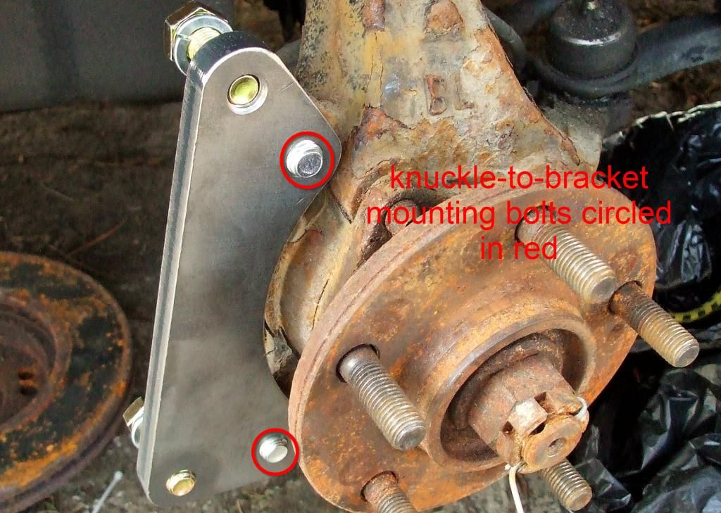
Photo 3. This photo shows how the RTM-made bracket is oriented on the steering knuckle. Note that the curved edge mirrors the curve of the hub and that the "pointy" end of the bracket is oriented upwards. You can also note the locations of the knuckle-to-bracket bolts (circled in red).
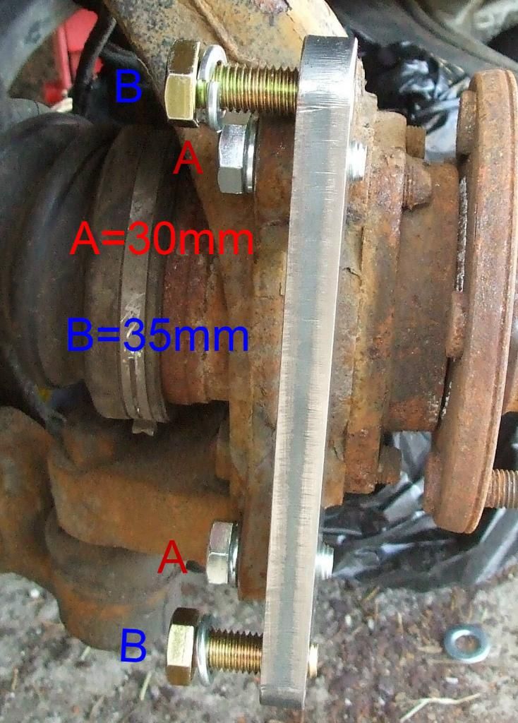
Photo 4. This is a side view of the RTM-made bracket mounted to the knuckle (using two knuckle-to-bracket bolts (labelled "A" in red)). The caliper-to-bracket bolts (labelled "B" in blue) are threaded into the bracket to show their eventual locations (though they would eventually have to be removed and passed through the mounting holes in the calipers, then threaded back into the bracket). Note the lock washers under each bolt head.
Installing 13" Cobra Rotor
We will take this time to remind you that the RTM-made VR4 brackets are designed to be used with 13" Ford Cobra rotors and NO OTHER ROTORS, INCLUDING VR4 ROTORS! Yes, that is correct and we think that deserves repeating: If you want to use our brackets with VR4 calipers you can NOT use VR4 rotors. If you want to mate VR4 rotors with VR4 calipers, you will have to source/make your own brackets, 'cause ours won't work.
NOTE: We strongly recommend using hubcentric rings to properly centre the centrebore of your Cobra rotors to the hub protrusion.
1) If you ordered your kit with hubcentric rings (or acquired them elsewhere), now is the time to install them.
2) If you ordered hubcentric rings from us, you will have received a total of four. Two of them have one size ID and the other two a different size ID. This is due to the fact that the diameter of the hub protrusion can be one of two different sizes. Determine which size fits on your hub protrusion by test fitting both sizes. We recommend removing any rust or debris from the protrusion (with sandpaper for example), then applying a bit of oil or grease. The correct hubcentric ring should slide over the protrusion with a certain degree of snugness, it shouldn't just "fall" into place.
3) Once you've determined the correct hubcentric ring, fully install it on the protrusion so that it bottoms out on the hub face.
4) Slide one of your Cobra rotors over the wheel studs and over the hub protrusion (which should contain a hubcentric ring).
5) Use at least two wheel (lug) nuts to snug the rotor against the hub face. There's no need to torque them down, just tighten them enough to prevent the rotor from moving.
Mounting Caliper to Bracket
1) If the pads have not yet been loaded to your caliper, load them now.
2) If you installed the caliper-to-bracket bolts into the bracket in a previous step (as depicted in Photos 3 & 4), remove them now.
3) Push the loaded caliper over the edge of the rotor and rotate it around the rotor until the mounting holes in the caliper line up with the threaded holes in the RTM-made bracket. Please note that the caliper will be mounted to the BACK side of the RTM-made bracket, such that the bracket will be between the caliper mounting holes and the rotor. Refer to Photo 5 for a good view of this area.
4) Make sure you are using the correct caliper for the side of the vehicle you are working on. To verify, the bleeder screw on the back of the caliper should be towards the top of the caliper (and NOT the bottom). Refer to Photo 5 for a good view of this area.
5) Install an M12 lock washer under the head each of two M12 x 35mm bolts.
6) Working from the back side of the caliper mounting holes, pass the two above bolt/lock washer assemblies through the caliper mounting holes and thread them into the appropriate threaded holes in the bracket. (Refer to Photos 3 & 4 to determine which threaded holes on the bracket to use, however, they should be the only holes remaining).
7) Firm up the bolts, but do NOT fully tighten yet.
Lining Caliper Up True to Centreline of Rotor Edge
When the caliper is snugged up against the RTM-made bracket, the brake pads should be pretty much centred to the edge of the rotor. That is, any gap between the pads and rotor face should be equal for the inboard and outboard pads. If they're not, the caliper will need to be "shimmed" a little inboard. Included with your hardware kit will be twelve flat washers to be used for this purpose. The shim washers are designed to be used on the caliper-to-bracket bolts and fit between the caliper and bracket. You should use an equal number of washers for each caliper-to-bracket bolt. Refer to Photo 5 for an image of a shim washer in place on the caliper.
Tightening Down Caliper to Bracket
Once you've determined that the caliper is oriented true to the centreline of the rotor edge, you can fully tighten down the caliper-to-bracket bolts. Torque to 65-70 ft/lbs.
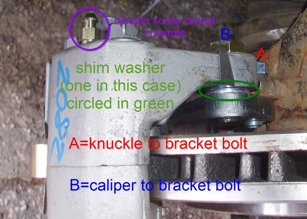
Photo 5. This view is looking down from the top of the caliper. This photo shows the location of the knuckle-to-bracket bolt (labelled "A" in red) and the caliper-to-bracket bolt (labelled "B" in blue). It also shows the location of the shim washer(s) (circled in green). The caliper's bleeder screw is circled in purple to indicate that the caliper is always mounted with the bleeder screw on the top of the caliper, NOT the bottom. If your bleeder screw is on the bottom, the caliper is on the wrong side of the vehicle.
Installing Brake Lines
The VR4 calipers use an M10x1.0 inverted flare port for the brake lines. 1g DSMs use this same style port, so stock 1g lines (or any other line that attaches to a stock 1g caliper) will work with the VR4 calipers. Stock 2g DSM and EVO I-III calipers use a M10x1.0 banjo port and is not compatible with the M10x1.0 inverted flare port used on VR4 calipers. Therefore, you'll need to use lines that terminate with an M10x1.0 inverted flare. RTM sells these lines for use with 2g DSM and EVO I-III.
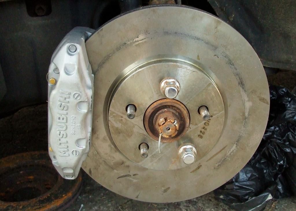
Photo 6. Caliper and rotor installed.
VR4 Big Brake Upgrade: DSM/EVO1-3
Categories
- New at RTM Racing
-
MITSUBISHI / EAGLE
- Eclipse / Talon / Laser
-
DSM: 1g (1990-94)
- Maintenance
- OEM Hardware
- Body & Exterior
-
Brakes
- Brake Upgrades
- Calipers
- Lines
- Rotors
- Pads
- Master Cylinder, Brake Booster, Proportioning Valve
- Parking Brake Cables, Hardware, etc
- Cooling
- Drivetrain & Transmission
- Engine
- Engine Management
- Exhaust
- Fuel
- Gauges
- Ignition & Electrical
- Intake
- Intercooler
- Interior
- Meth/Water Injection
- Suspension & Steering
- Turbo
- Wheels
- Safety
- Special Tools
-
DSM: 2g (1995-99)
- Maintenance
- OEM Hardware
- Body & Exterior
-
Brakes
-
Brake Upgrades
- 3000GT-VR4/Cobra Front Big Brake Upgrade
- 3000GT-VR4/Genesis Front Big Brake Upgrade
- Wilwood Front Big Brake Upgrade
- EVO 5-9 (Brembo) Front Big Brake Upgrade
- CTS-V (Brembo) Front Big Brake Upgrade
- Ford Cobra Front Big Brake Upgrade
- Outlander Front Big Brake Upgrade
- EVO 5-9 (Brembo) Rear Big Brake Upgrade
- Calipers
- Lines
- Rotors
- Pads/Shoes
- Master Cylinder, Brake Booster, Proportioning Valve
- Parking Brake Cables, Hardware, etc
- Brake Fluids
-
Brake Upgrades
- Cooling
- Drivetrain & Transmission
- Engine
- Engine Management
- Exhaust
- Fuel
- Gauges
- Ignition & Electrical
- Intake
- Intercooler
- Interior
- Meth/Water Injection
- Suspension & Steering
- Turbo
- Wheels
- Safety
- Special Tools
- Penetrants, Anit-Seize, Rust Removal
- DSM: 2gNT (1995-99)
-
EVO: I-III (1992-96)
- Maintenance
- OEM Hardware
- Body / Exterior
- Brakes
- Cooling
- Drivetrain & Transmission
- Engine
- Engine Management
- Exhaust
- Fuel
- Gauges
- Ignition & Electrical
- Intake
- Intercooler
- Interior
- Meth/Water Injection
- Suspension & Steering
- Turbo
- Wheels
- Safety
- Special Tools
- Penetrants, Anit-Seize, Rust Removal
-
EVO: IV-VI (1996-01)
- Maintenance
- OEM Hardware
- Body / Exterior
- Brakes
- Cooling
- Drivetrain & Transmission
- Engine
- Engine Management
- Exhaust
- Fuel
- Gauges
- Ignition & Electrical
- Intake
- Intercooler
- Interior
- Meth/Water Injection
- Suspension & Steering
- Turbo
- Wheels
- Safety
- Special Tools
- Penetrants, Anit-Seize, Rust Removal
-
EVO: VII-IX (2001-07)
- Maintenance
- Body / Exterior
- Brakes
- Cooling
- Drivetrain & Transmission
- Engine
- Engine Management
- Exhaust
- Fuel
- Gauges
- Ignition & Electrical
- Intake
- Intercooler
- Interior
- Meth/Water Injection
- Suspension & Steering
- Turbo
- Wheels
- Safety
- Special Tools
- Penetrants, Anit-Seize, Rust Removal
-
EVO: X (2008-15)
- Maintenance
- OEM Hardware
- Body & Exterior
- Brakes
- Cooling
- Drivetrain & Transmission
- Engine
- Engine Management
- Exhaust
- Fuel
- Gauges
- Ignition & Electrical
- Intake
- Intercooler
- Interior
- Meth/Water Injection
- Suspension & Steering
- Turbo
- Wheels
- Safety
- Special Tools
- Penetrants, Anit-Seize, Rust Removal
- Galant VR4 (1988-97)
- 3000GT (1991-99)
- Lancer / Ralliart
- OEM Hardware
-
Universal
- Air Filters
- Anti-Seize
- Banjo Bolts & Fittings
- Batteries & Battery Boxes
- Blowoff Valves
- Body Accessories
- Boost Controllers
- Brake Accessories
- Catch Cans
- Couplers
- CV Boot Clamps
- Engine Bay Grounding Kits
- Engine Management
- Exhaust
- Fire Extinguishers
- Fluids
- Fuel
- Fuses
- Gauges
- Heat Shields, Wraps, Coatings
- Hood Pins & Latches
- Hose
- Hose Clamps
- Hose Ends & Fittings
- Intercooler
- Interior Accessories
- Magnetic Oil Drain Plugs
- Meth/Water Injection
- Oil & Transmission Coolers
- Penetrants
- Plumbing
- Racing Seats
- Rad Fans, Rad Caps, Accessories
- Rust Removal
- Scan Tools (OBDII)
- Shift Knobs
- Silicone Couplers
- Surge Tanks
- T-Bolt Clamps
- Throttle Bodies
- Turbo
- Turbo Timers
- V-Band Clamps
- Vacuum Hose
- Wastegates
- Weld Bungs
- Wheel Accessories
- Wideband O2
- Window Stickers
- Windshield Wipers
- Y-Blocks
- Hard-to-Find Parts
- Bargain Bin
- Made by RTM
- Search don't Surf
Cart is empty
Manufacturers

Users online:
175
anonymous customer(s)
Powered by X-Cart shopping cart software
Copyright © 2003-2024 RTM Racing